







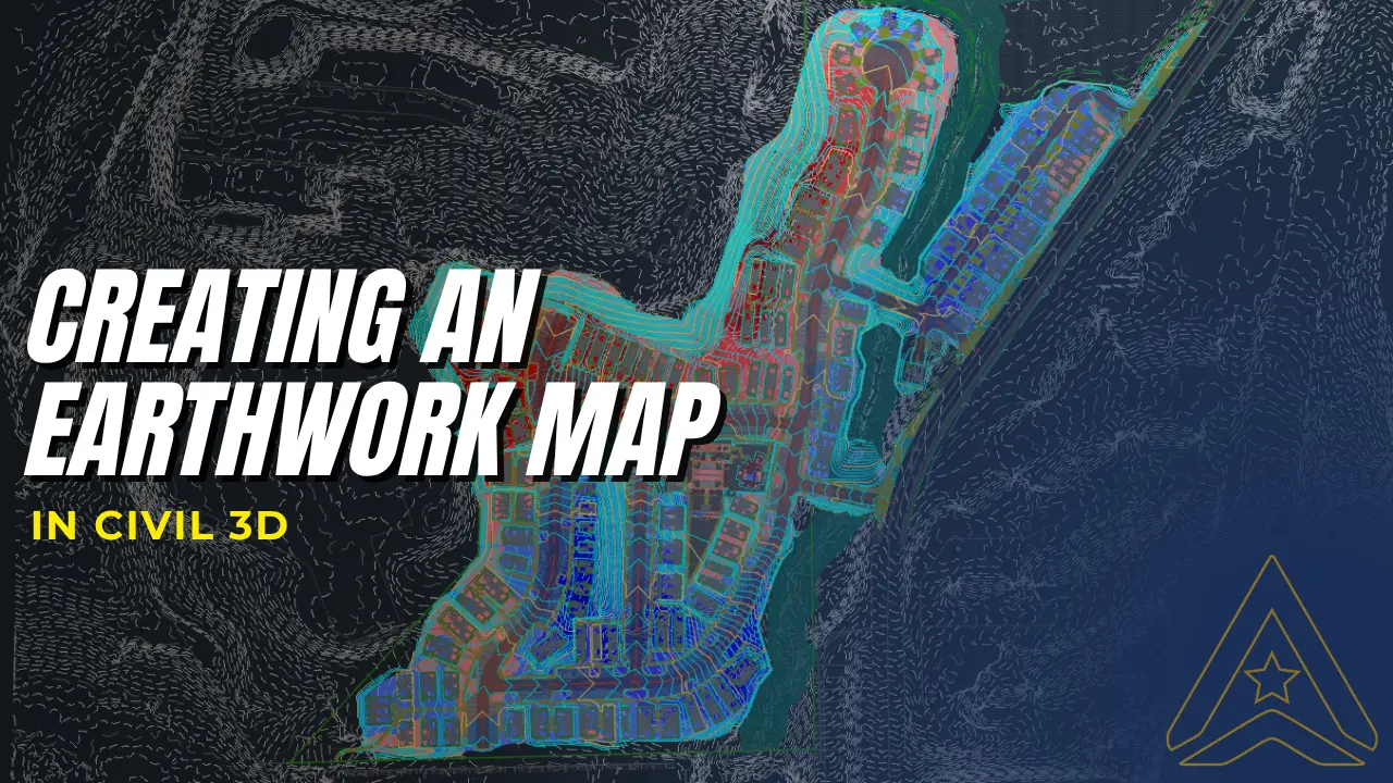
In grading projects, earthwork is rarely just a quantity calculation. It is a design, cost, coordination, and construction planning challenge at the same time. A project team may know the total cut and fill volume, yet still struggle to see where the deepest cut occurs, which areas require significant fill, and how those conditions may affect hauling, staging, and grading decisions.
This is where an Earthwork Map for Cut and Fill Analysis in Civil 3D becomes valuable. For AXANH, an Earthwork Map is not only a Civil 3D output. It is a visual decision-support deliverable that helps owners, civil engineers, contractors, and land development teams understand how a site will be reshaped before construction begins.
By combining Existing Ground data, Finished Ground design, volume surface analysis, and color-coded depth ranges, AXANH helps project teams review grading decisions earlier, communicate cut/fill conditions more clearly, and control earthwork-related risks with greater confidence.
What Is an Earthwork Map for Cut and Fill Analysis in Civil 3D?
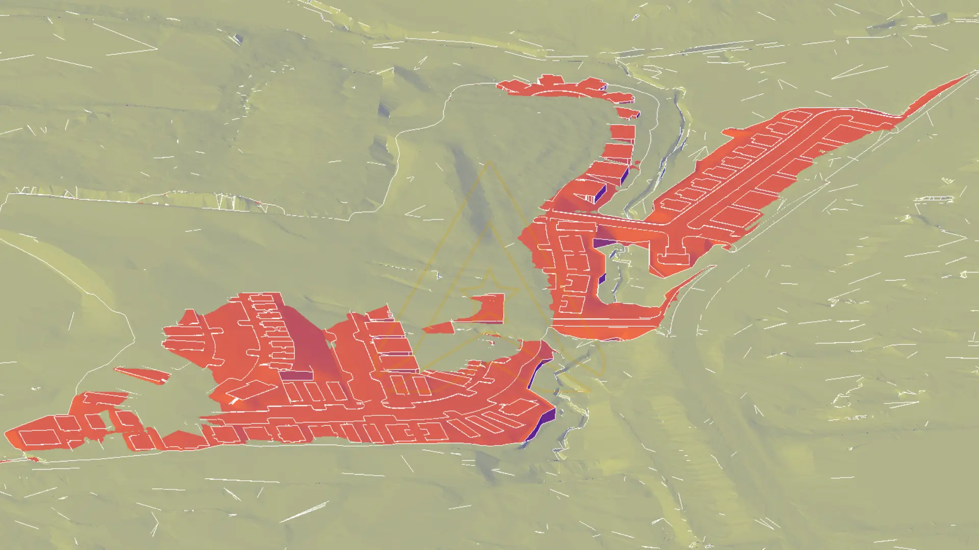
An Earthwork Map in Civil 3D is a color-coded drawing that visualizes the elevation difference between the Existing Ground surface and the Finished Ground surface. By using a volume surface and depth range analysis, it shows where cut and fill occur, how intense each zone is, and how earthwork quantities may influence grading decisions.
Instead of presenting cut and fill only as numbers in a quantity report, an Earthwork Map translates the data into a plan-view graphic. Areas of excavation can be shown in one color range, while areas of embankment or fill can be shown in another. The deeper or more significant the cut/fill condition, the easier it becomes for the project team to identify critical zones.
In this context, an Earthwork Map for Cut and Fill Analysis in Civil 3D becomes a practical bridge between surface modeling, volume calculation, and grading design review.
This makes the drawing useful not only for civil engineers, but also for owners, contractors, project managers, cost estimators, and non-technical stakeholders who need to understand the practical implications of grading design.
Why Cut and Fill Analysis Needs More Than Quantity Tables
A cut and fill quantity table is essential, but it does not always tell the full story.
Two grading designs may have similar net volumes, yet their construction impact can be very different. One option may have shallow, evenly distributed cut and fill across the site. Another may include deep excavation in one area and high fill in another. On paper, the total numbers may look acceptable. In the field, the second option may require more hauling, more compaction control, more staging, and more coordination.
Quantity totals do not show spatial distribution
A total cut volume and total fill volume can help the team understand the overall earthwork balance, but they do not show where the work happens. For a contractor, location matters. A large fill zone far from available cut material may create additional hauling requirements. A deep cut zone near a boundary, existing utility, drainage path, or access road may require further review.
Conventional grading drawings may not communicate earthwork intensity
A grading plan shows contours, spot elevations, slopes, drainage intent, and design levels. However, it may not immediately show how much earth must be removed or added at each location. For experienced civil engineers, the implication may be visible after careful review. For owners or other stakeholders, it can be harder to interpret.
A color-coded Earthwork Map closes this communication gap. It highlights areas that require attention: minor grading zones, moderate cut/fill areas, deep excavation, and high embankment. This helps the design conversation move from “What does the number say?” to “Where should we focus our review?”
AXANH’s Civil 3D Workflow for Creating an Earthwork Map
AXANH’s workflow is built around a simple principle: the value of an Earthwork Map depends on the quality of the surfaces behind it.
A visually attractive map is not enough. The Existing Ground surface must be reliable. The Finished Ground surface must reflect the current grading design. The volume surface must be created with consistent boundaries and assumptions. The final drawing must be clear enough for both engineers and stakeholders to review.
Step 1: Build the Existing Ground surface from survey data
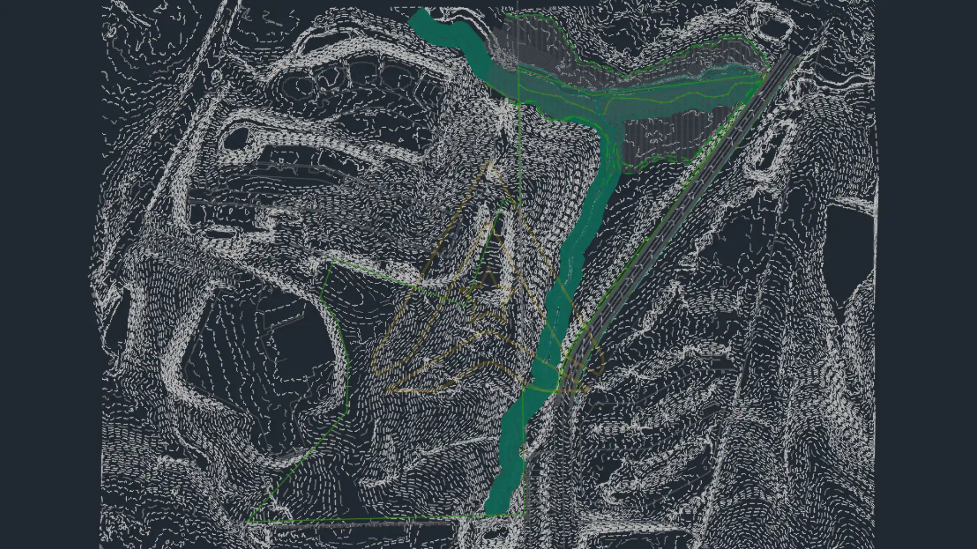
The first step is creating the Existing Ground surface, often referred to as EG. This surface represents the natural or current condition of the site before proposed grading work begins.
Depending on the information provided by the client, the EG surface may be developed from topographic survey points, contours, breaklines, spot elevations, terrain data, or other survey-related information. In Civil 3D, this surface becomes the baseline for every earthwork calculation that follows.
Accuracy at this stage is critical. If the Existing Ground surface is incomplete, poorly controlled, or built from inconsistent data, the cut and fill results will also be unreliable. This can lead to misleading volume calculations, incorrect grading assumptions, and avoidable coordination issues later in the project.
Step 2: Develop the Finished Ground surface from grading design
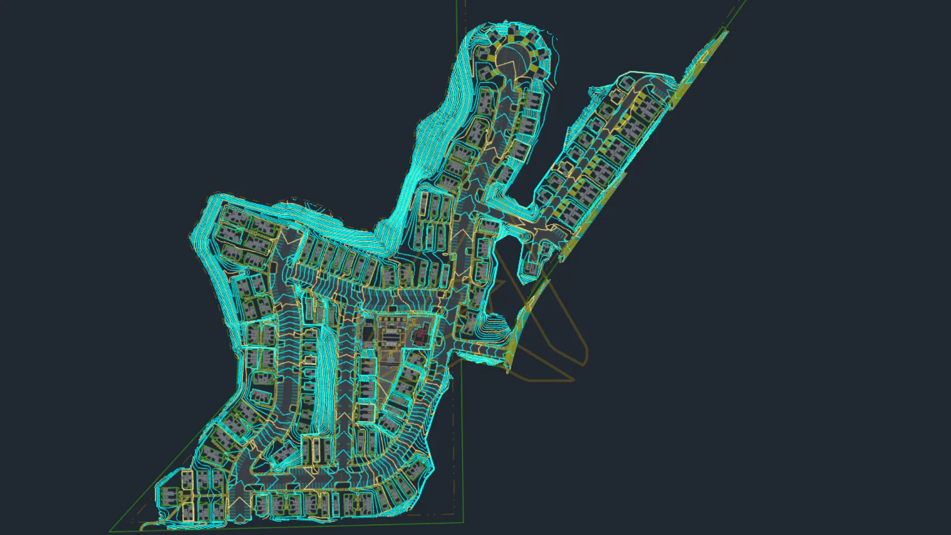
After the Existing Ground surface is established, the next step is creating the Finished Ground surface, often referred to as FG. This surface represents the proposed final condition of the site after grading and earthwork activities are completed.
The FG surface is not just a collection of final elevations. It reflects the design intent of the project: building pads, roadways, parking areas, sidewalks, landscape zones, drainage direction, tie-in conditions, accessibility requirements, utility coordination, and platform elevations.
A well-developed FG surface allows the project team to compare design intent against existing terrain. It also provides a basis for reviewing whether the proposed grading design is efficient, constructible, and aligned with project cost expectations.
Step 3: Create the Volume Surface between EG and FG
Once both EG and FG surfaces are prepared, AXANH creates a Volume Surface in Civil 3D. This surface compares the Existing Ground and Finished Ground models to determine where cut and fill occur across the site.
- Where the Finished Ground is lower than the Existing Ground, the site requires cut.
- Where the Finished Ground is higher than the Existing Ground, the site requires fill.
- Where the difference is minimal, only minor grading adjustment may be needed.
Civil 3D’s volume tools allow project teams to compare surfaces and produce cut/fill quantity information. Autodesk’s support article on the Civil 3D Volumes Dashboard explains how Civil 3D can be used to create cut and fill volume tables from surface comparison.
Step 4: Apply depth range analysis and color-coded mapping
The Volume Surface provides the data. The Earthwork Map makes the data understandable.
AXANH applies depth range analysis to classify areas by the amount of cut or fill. Instead of showing one general cut zone and one general fill zone, the map can be organized into multiple depth ranges.
| Map Range | What It Helps the Team Understand |
|---|---|
| Minor cut / minor fill | Areas with limited grading impact and lower review priority. |
| Moderate cut / moderate fill | Zones that may influence hauling, transitions, and quantity control. |
| Deep cut | Areas that may require review of excavation risk, slopes, drainage, or constructability. |
| High fill | Areas that may require review of material availability, compaction, settlement, and staging. |
A good Earthwork Map should not overwhelm the viewer. The color system must be readable, the legend must be clear, and the drawing should support decision-making rather than simply display software output.
Step 5: Review cut/fill balance and adjust grading elevations
After the Earthwork Map is created, the design team reviews both the visual distribution and the total cut/fill quantities.
If the volumes are significantly unbalanced, the team may evaluate whether Finished Ground elevations can be adjusted. For example, a building pad, roadway profile, parking area, or platform elevation may be slightly raised or lowered to improve the relationship between cut and fill. Autodesk’s tutorial on balancing cut and fill volumes in Civil 3D explains the use of grading groups and surface volumes for cut/fill calculation.
In real projects, this review must be handled carefully. Earthwork balance is important, but it cannot override drainage, accessibility, roadway design, utility coordination, permitting constraints, or site functionality.
How an Earthwork Map Supports Better Grading Decisions
An Earthwork Map becomes most valuable when it helps the project team make better decisions earlier. In grading and land development projects, late changes can be expensive. If deep cut or high fill areas are discovered too late, the project may require redesign, additional cost review, contractor clarification, or revised construction planning.
Visualizing deep cut and high fill areas earlier
The most immediate benefit of an Earthwork Map is visibility. Project teams can quickly see where the site requires major excavation or embankment. This helps engineers focus their review on the most critical zones instead of treating the entire site as one uniform grading problem.
For example, a deep cut zone may require review of slope transitions, retaining conditions, rock excavation risk, drainage impacts, or haul routes. A high fill zone may require review of compaction, settlement considerations, material availability, and construction sequencing.
Supporting earthwork balance and cost control
Earthwork imbalance can increase project cost through import/export requirements, additional hauling, stockpile management, and construction inefficiency. While an Earthwork Map does not replace contractor pricing or geotechnical review, it does support earlier cost awareness.
- Can proposed elevations be adjusted without compromising drainage?
- Are large fill zones avoidable?
- Is cut material located close enough to fill areas?
- Are there isolated earthwork hotspots that need special review?
- Should the site be divided into bounded analysis zones or phases?
Improving communication between engineers, owners, and contractors
Civil 3D data can be highly technical. Stakeholders may not always have the time or background to interpret surface models, volume reports, or detailed grading plans.
An Earthwork Map improves communication by turning technical data into a visual story. It helps the owner understand cost drivers. It helps contractors anticipate earthwork intensity. It helps engineers explain why certain grading adjustments are recommended. It helps project managers coordinate decisions across disciplines.
What Should Be Included in a Professional Earthwork Map?
A professional Earthwork Map should be more than a colored surface screenshot. It should be a structured technical drawing that project teams can review, reference, and discuss.
| Component | Purpose |
|---|---|
| Cut/fill color legend | Defines which colors represent cut, fill, and depth ranges. |
| Volume summary | Connects visual distribution with cut, fill, and net volume control. |
| Critical zone callouts | Highlights deep cut, high fill, boundary concerns, or review areas. |
| Surface references | Clarifies which EG and FG surfaces were used for comparison. |
| Assumptions and boundaries | Helps avoid misinterpretation of the analysis area and volume results. |
When Project Teams Should Use an Earthwork Map
Not every project requires a complex Earthwork Map. For small, flat, straightforward sites, a basic cut/fill report may be sufficient. However, the value of Earthwork Map analysis increases significantly when the project has terrain complexity, cost sensitivity, or multiple stakeholders.
Land development projects with uneven terrain
Residential subdivisions, commercial sites, campuses, industrial parks, and mixed-use developments often require careful grading coordination. When the site includes slopes, drainage constraints, road networks, pads, parking areas, and multiple tie-ins, earthwork can quickly become one of the most important design considerations.
For broader context on this challenge, AXANH has also discussed how earthwork optimization for complex sites affects grading cost, rework, and project feasibility.
Infrastructure projects with grading constraints
Infrastructure projects may involve roads, utilities, drainage systems, public works, or site access improvements. These projects often require coordination between horizontal geometry, vertical design, drainage performance, right-of-way limits, and existing conditions.
Projects requiring early cost estimation and haul planning
When earthwork cost is a major concern, early visualization is valuable. Owners and contractors need to understand not only the amount of material, but also where material is located and how it may move across the site.
Common Mistakes in Cut and Fill Mapping
Creating an Earthwork Map is not difficult in concept, but it requires discipline. Several common mistakes can reduce the reliability of the analysis.
- Using inaccurate Existing Ground data: poor survey input leads to unreliable downstream volume results.
- Comparing surfaces with inconsistent boundaries: mismatched extents can include unintended areas or miss important zones.
- Relying on volume totals alone: a balanced net volume does not always mean soil movement is efficient.
- Not updating the map after grading revisions: outdated maps can lead to outdated design decisions.
How AXANH Turns Civil 3D Data into Actionable Earthwork Maps
AXANH supports international project teams by transforming grading data into clear, review-ready earthwork deliverables. The value is not only in operating Civil 3D. The value is in understanding how technical outputs influence real project decisions.
A volume surface is useful. A readable Earthwork Map is more useful. A map that helps the team adjust design direction before cost or construction issues emerge is even more valuable.
AXANH’s approach is supported by three operating principles:
- Technical clarity: surfaces, boundaries, depth ranges, and assumptions must be clear.
- Quality discipline: deliverables should be reviewed before they are shared with project stakeholders.
- Decision usefulness: drawings should help teams understand what to review, not simply display data.
This approach aligns with AXANH’s broader technical capability model, where civil engineering, digital delivery, documentation, QA/QC, and coordination are treated as connected parts of one delivery system.
Practical Review Checklist for an Earthwork Map
Before using an Earthwork Map for design review, project teams should confirm that the drawing is technically reliable and aligned with the latest design information.
- The Existing Ground surface is based on reliable and current survey data.
- The Finished Ground surface reflects the latest grading design.
- The analysis boundary is clearly defined.
- Cut and fill color ranges are easy to understand.
- The volume summary matches the correct surface comparison.
- Critical cut/fill zones are identified for review.
- Assumptions and exclusions are documented.
- The map version corresponds to the current design issue.
- Any grading adjustment is reviewed against drainage, accessibility, utility, and permitting requirements.
Need clearer cut and fill decisions for your grading project?
AXANH can help project teams turn Civil 3D surface data into Earthwork Maps that support visual review, quantity control, grading coordination, and earlier decision-making.
Conclusion: From Earthwork Data to Project Clarity
An Earthwork Map is more than a colored drawing. It is a bridge between technical surface data and practical project decision-making.
For civil engineers, it provides a clearer way to review cut/fill distribution. For owners, it helps explain where earthwork cost may come from. For contractors, it supports early understanding of excavation, embankment, hauling, and sequencing conditions. For project teams, it reduces ambiguity and improves coordination before grading decisions become harder to change.
In Civil 3D, the process begins with reliable Existing Ground and Finished Ground surfaces. It continues through volume surface analysis, depth range classification, and visual mapping. But the real value comes from how the map is interpreted, reviewed, and used to improve the design.
When prepared with reliable EG and FG surfaces, an Earthwork Map for Cut and Fill Analysis in Civil 3D helps project teams move from raw earthwork data to clearer grading decisions.
At AXANH, effective grading design is not only about achieving final elevations. It is about creating solutions that are technically sound, visually clear, cost-aware, and practical for construction. With Earthwork Map analysis in Civil 3D, project teams can better understand site conditions, optimize cut and fill decisions, and move from terrain complexity toward more confident project delivery.
