








LOD in infrastructure BIM defines how much reliance project teams can place on modeled information. A highly detailed 3D representation of a roadway, grading surface, or underground utility network may look complete, but visual detail alone does not establish whether its geometry is sufficiently defined for design review, coordination, quantity takeoff, or construction planning.
For engineering firms, project managers, and BIM leads, this distinction has direct consequences. When Level of Development (LOD) requirements are unclear, different teams may make different assumptions about model readiness, responsibility, and the information included in a deliverable.
These challenges become especially relevant when engineering work involves teams operating across different markets. U.S. BIM guidance and Vietnam’s published BIM implementation guidance both use LOD concepts, but they do not necessarily organize model development expectations in the same way.
This article examines the commonly referenced LOD 100, 200, 300, 350, 400, and 500 definitions, compares U.S. and Vietnamese guidance, and explains how LOD requirements can be considered in infrastructure workflows involving Autodesk Civil 3D.
Key takeaway: LOD describes the development and permitted reliance on an individual model element. It is not a measure of 3D detail.
What Does LOD Mean in Infrastructure BIM?
Level of Development (LOD) is a framework for describing how far a model element has been developed and the extent to which its represented characteristics can be relied upon.
The BIMForum Level of Development Specification 2025 provides a reference for communicating the content and reliability of model elements across project participants.
Its value lies in making expectations explicit. Instead of assuming that a modeled object is ready for every downstream use, project teams can identify which characteristics are sufficiently developed and which remain approximate or unresolved.
Level of Detail vs. Level of Development
Although the terms are sometimes confused, they address different questions.
| Level of Detail | Level of Development |
|---|---|
| Describes the amount of detail represented in a model. | Describes how reliably the represented characteristics can be used. |
| An object may appear complex while retaining approximate or assumed dimensions. | An object may use relatively simple geometry while meeting an agreed development requirement. |
| How much detail is shown? | What information can the receiving team reasonably rely on? |
Consider a modeled storm drainage network. Its pipes, structures, and fittings may all be visible in three dimensions. Yet if pipe diameters, invert elevations, or alignments are still based on preliminary assumptions, the model should not be treated as having established those characteristics to LOD 300.
Conversely, a simpler pipe network may satisfy the required LOD when its relevant geometry has been developed to the accuracy and reliability expected for the intended use.
LOD applies to model elements rather than automatically defining an entire model. A single infrastructure model can contain terrain surfaces, road corridors, drainage systems, and specialty components at different Levels of Development.
LOD 100–500: Understanding the Different Levels of Development
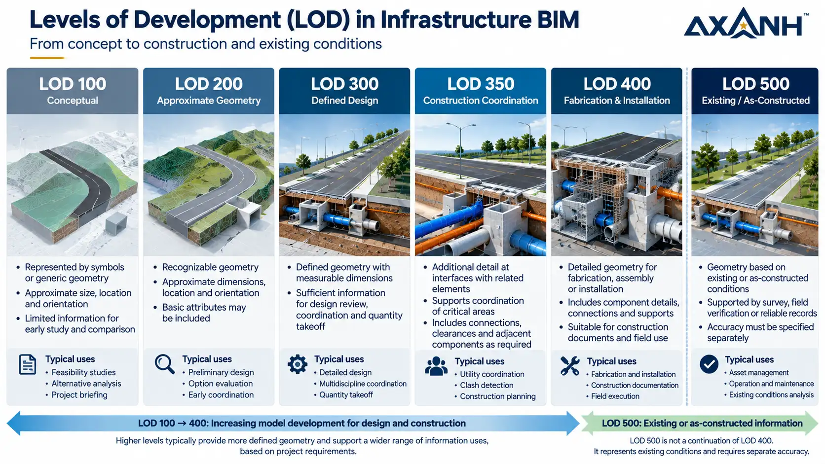
The commonly referenced LOD levels describe different states of model development and information reliability. They should be interpreted in relation to the relevant element definition and the requirements established for the project.
| LOD | Meaning and Practical Application |
|---|---|
| LOD 100 | Conceptual representation. Elements may be represented by symbols or generalized information. Values derived from the model remain approximate. |
| LOD 200 | Approximate geometry. Elements have recognizable geometry, while dimensions, locations, and orientations may still be approximate. |
| LOD 300 | Defined design geometry. Relevant dimensions, shapes, and positions are sufficiently established to be measured from the modeled element within its defined scope. |
| LOD 350 | Construction-level coordination. The model includes the interfaces with adjacent or dependent elements needed for the intended coordination activities. |
| LOD 400 | Fabrication and installation. Elements contain the modeled geometry required for fabrication, assembly, or installation within the agreed scope. |
| LOD 500 | Existing or as-constructed conditions. Geometry reflects observed, field-verified, or appropriately interpolated conditions, with its accuracy separately specified. |
One common misconception is that every model must progress sequentially through all LOD levels. In practice, the required development depends on the element, the intended information use, and the agreed project deliverables.
Why LOD 500 Is Different
LOD 500 does not simply mean a more detailed LOD 400 model.
As clarified in the BIMForum specification, LOD 500 refers to geometry determined from existing or as-constructed conditions rather than the design of a future element. The accuracy of that geometry must be stated separately.
This distinction is important for infrastructure projects involving existing utility networks, surveyed ground conditions, or as-built documentation. A modeled existing feature may be geometrically sophisticated but still carry uncertainty inherited from its source survey or field records.
Neither visual completeness nor the LOD label alone resolves that uncertainty.
How LOD Requirements Are Established in U.S. Infrastructure Projects
In the United States, teams may draw on AIA BIM documentation, BIMForum guidance, owner requirements, agency specifications, and project-specific BIM Execution Plans (BEPs).
An important principle of the BIMForum framework is that LOD levels are not automatically assigned to fixed design phases.
The required development level, responsible model element author, intended use, and delivery milestone should be defined within the project’s governing documents.
Illustrative Applications Across Infrastructure Design
- LOD 100–200: Early alignment studies, conceptual grading, preliminary infrastructure arrangements, and comparisons of design alternatives.
- LOD 300: Defined geometry for selected surfaces, alignments, profiles, corridors, and utility networks.
- LOD 350: Detailed interfaces at roadway intersections, utility crossings, drainage connections, and other locations requiring additional coordination.
- LOD 400: Selected fabricated or prefabricated components where fabrication, assembly, or installation information is required.
- LOD 500: Existing or as-constructed features supported by an appropriate observation, verification, or documentation process.
These examples illustrate how a project team might allocate development effort. They are not a universal LOD schedule for U.S. infrastructure projects.
For example, a drainage network developed to LOD 300 may still contain unresolved conflicts with adjacent utilities. More detailed coordination at a crossing could call for LOD 350 characteristics, but that does not replace hydraulic calculations, code compliance checks, or engineering QA/QC.
For broader context on infrastructure BIM in the United States, see the Federal Highway Administration’s BIM for Infrastructure resources.
How Vietnam’s BIM Guidance Approaches LOD for Infrastructure
Vietnam provides a useful comparison because its published BIM guidance includes illustrative development levels associated with design stages.
On April 2, 2021, Vietnam’s Ministry of Construction issued Decision No. 347/QD-BXD, accompanied by detailed BIM implementation guidance for buildings and urban technical infrastructure.
Appendix 03 of that guidance, printed page 115, includes an example table showing model development levels for infrastructure elements across three design stages.
Illustrative LOD Matrix in Vietnam’s Ministry of Construction Guidance
The following levels correspond, in sequence, to Basic Design → Technical Design → Construction Drawing Design.
| Infrastructure Element | LOD by Design Stage |
|---|---|
| Terrain | 200 → 300 → 300 |
| Site Grading and Filling | 200 → 300 → 350 |
| Foundation Excavation | 200 → 300 → 300 |
| Piles | 200 → 300 → 350 |
| Roads and Railways | 300 → 350 → 400 |
| Ancillary Equipment | 200 → 300 → 350 |
| Existing Pipe Networks | 200 → 300 → 300 |
| Water Supply and Drainage Systems | 200 → 300 → 350 |
Source: Vietnam Ministry of Construction, Detailed BIM Implementation Guidance, Appendix 03, printed page 115. This is an illustrative reference table, not a mandatory LOD matrix for every project.
What the Vietnam Example Reveals
The matrix assigns different development levels to different element groups within the same design stage.
For example, it lists LOD 350 for water supply and drainage systems and LOD 400 for roads and railways at the construction drawing design stage.
However, these examples should not be treated as universal deliverable requirements. The applicable model scope, information requirements, contractual responsibilities, and technical criteria must still be established for the individual project.
Vietnam’s Current BIM Regulatory Context
Vietnam’s Decree No. 217/2026/ND-CP, effective July 1, 2026, replaced Decree No. 175/2024/ND-CP.
Article 8 addresses BIM application in construction activities. Among its provisions, the scope, implementation content, and necessary information requirements for BIM are to be established through agreements in the relevant contracts at each project stage.
For international project teams, the practical distinction is that a requirement to apply BIM does not, by itself, establish one LOD for every element or deliverable.
When collaborating across jurisdictions, the contractual information requirements and approved project documents remain essential to interpreting what the model must contain.
Three Important Differences Between U.S. and Vietnam LOD References
The comparison is less about which country requires a more sophisticated model and more about how development expectations are described and assigned.
1. LOD and Design Stages Are Not Always Linked the Same Way
Vietnam’s 2021 BIM guidance provides an illustrative relationship between LOD and basic design, technical design, and construction drawing design stages.
BIMForum, by contrast, does not prescribe a fixed LOD for each project phase. Model development expectations are established around the specific elements, intended uses, and deliverables.
For a project manager, this means a milestone described as “detailed design” or “construction documentation” does not automatically provide enough information to determine model readiness.
2. The Same LOD Number May Lead to Different Deliverable Expectations
LOD 400 offers a particularly useful example.
Vietnam’s illustrative matrix assigns LOD 400 to roads and railways at the construction drawing design stage. The BIMForum framework emphasizes the characteristics of model elements needed for fabrication, assembly, and installation.
The numerical label is the same, but the element-specific information and expected output may differ.
The practical response is to define required geometry, modeled interfaces, deliverable formats, and acceptance criteria rather than relying on an LOD number alone.
3. Model Development Does Not Replace Source-Data Reliability
Existing underground utilities introduce a separate concern: the reliability of the information from which the model is created.
In U.S. infrastructure practice, Subsurface Utility Engineering (SUE) methods and standards such as ASCE 38-22 can help teams characterize and manage the quality of existing utility information.
A modeled utility may satisfy an agreed geometric development requirement while its original location data remains uncertain.
That uncertainty needs to be communicated and managed independently of the model’s LOD designation.
For cross-border delivery teams, the central question is therefore not simply whether two models carry the same LOD label. It is whether they communicate the same level of usable information under the same agreed assumptions.
Applying LOD in Autodesk Civil 3D Infrastructure Workflows
Consider an illustrative U.S. residential land development project involving internal roads, grading, storm drainage, sanitary sewer, and water distribution systems.
The design team uses Autodesk Civil 3D to develop surfaces, alignments, profiles, road corridors, and pipe networks.
Rather than requiring every modeled element to achieve LOD 350, the project team can define development requirements by element group and intended use.
An Illustrative LOD Allocation Matrix
| Model Element Group | Illustrative Development Requirement |
|---|---|
| Existing / Proposed Surfaces | LOD 300 may be considered for sufficiently defined geometry. Existing-condition reliability must also be assessed against the survey source and documented accuracy. |
| Grading & Road Corridors | LOD 300 for defined design geometry, with LOD 350 characteristics where intersections, curbs, drainage inlets, or adjacent interfaces require additional coordination. |
| Storm / Sanitary Pipe Networks | LOD 300 for defined pipe geometry, with LOD 350 coordination at crossings, structures, and connections requiring interface verification. |
| Water Distribution | LOD 300 where appropriate, with LOD 350 characteristics at utility connections or constrained crossings. |
| Precast / Specialty Components | LOD 400 where fabrication, assembly, or installation requirements make that level of geometric development necessary. |
Illustrative allocation for discussion; each project sets its own matrix.
When Does Additional Model Development Become Necessary?
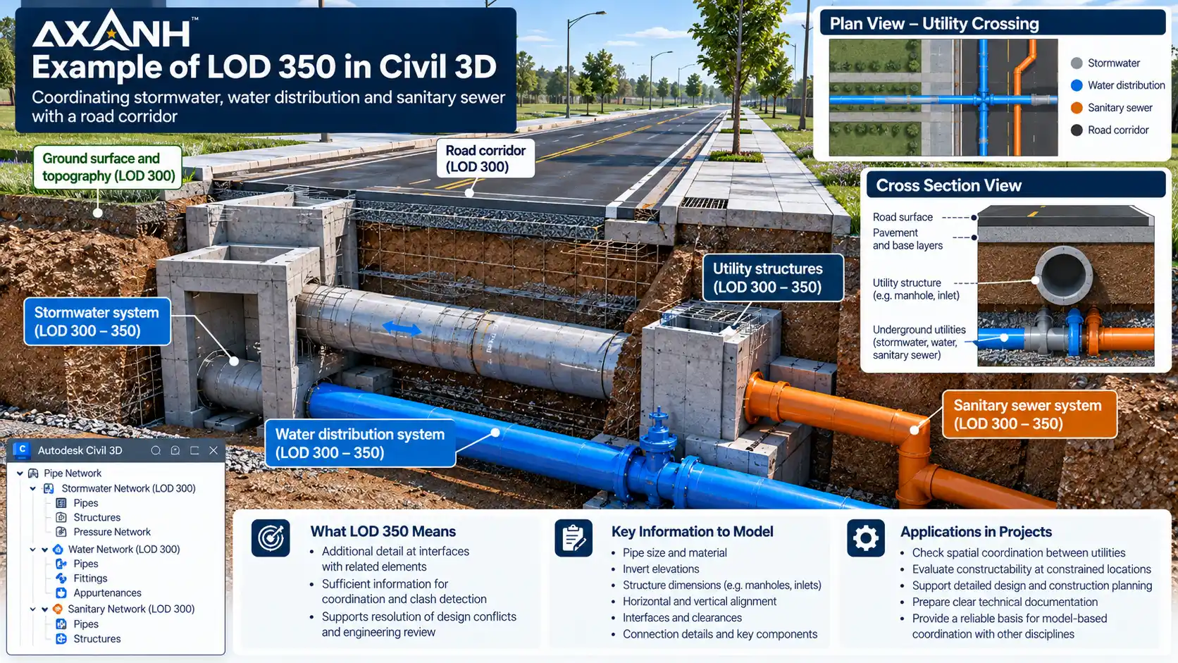
Imagine a storm drainage pipe crossing a water distribution line.
The two systems may already have defined alignments, diameters, and elevations at LOD 300. However, meaningful coordination may require additional information about the physical interfaces, structure dimensions, connections, and available separation at the crossing.
Those requirements can justify a higher level of development for selected interfaces without requiring the entire utility network to be modeled to the same level.
This is an important distinction for engineering production planning. The objective is to direct modeling effort toward information that supports a real decision, review, or construction-related coordination activity.
In Civil 3D, data such as alignments, profiles, roadway geometry, pipe diameters, invert elevations, and utility crossing locations must be assessed according to their actual design status.
Software can create and manage model geometry. It does not independently establish that the information has achieved LOD 300, LOD 350, or any other agreed development level.
LOD, Level of Information Need, and QA/QC: Why the Distinction Matters
Level of Development is only one component of effective model information management.
ISO 7817-1:2024 establishes concepts and principles for defining the Level of Information Need (LOIN).
LOIN focuses on specifying the information required for a particular purpose or exchange, including geometric information, properties, and documentation as applicable.
| Concept | Primary Question |
|---|---|
| LOD | How far has the model element been developed, and which represented characteristics can be relied upon? |
| LOIN | What information is needed for this specific purpose or information exchange? |
| QA/QC | Has the engineering information been checked against the relevant requirements and acceptance criteria? |
For example, a team checking the interaction between two underground utilities may need pipe locations, outside diameters, elevations, and clearances.
It may not need every fabrication detail if the immediate purpose is to identify potential spatial conflicts.
Conversely, a pipe network with geometry developed to LOD 300 does not automatically establish that hydraulic capacity, drainage performance, or code compliance has been verified.
Those remain engineering design and quality-control responsibilities.
Vietnam’s TCVN 14177-1:2024 and TCVN 14177-2:2024 standards for BIM information management provide additional context for structured information requirements and responsibilities within the Vietnamese standards environment.
For project leadership, LOD, LOIN, and QA/QC should therefore be treated as connected but distinct controls. A clearly developed model is most useful when its information purpose, review status, and limits are understood by the teams receiving it.
Five Questions to Resolve Before Agreeing on Infrastructure BIM LOD Requirements
Before assigning development levels to an infrastructure model, project teams should establish what each deliverable is expected to support.
- Which model elements are included? Are surfaces, corridors, pipe networks, manholes, and other relevant components clearly identified?
- What decisions must the model support? Is the intended use design review, quantity takeoff, spatial coordination, construction planning, or asset management?
- What LOD is required, and when? Are development expectations defined by element group and information delivery milestone?
- What information is verified? Are survey sources, design assumptions, positional accuracy, and limitations documented and communicated?
- Who is accountable for acceptance? Are model authors, reviewers, QA/QC criteria, exchange formats, and approval responsibilities established?
These questions can be translated into a Model Element Table, BIM Execution Plan, or project-specific information requirements.
The resulting agreement should allow both the model author and receiving team to understand what is being delivered and what the information can reasonably be used for.
That clarity becomes particularly valuable when work moves across offices, disciplines, organizations, or international delivery teams.
Frequently Asked Questions About LOD in Infrastructure BIM
Is LOD 300 sufficient for construction documentation?
LOD 300 may be appropriate for many defined design elements, but it does not automatically satisfy all construction documentation requirements. Drawings, calculations, specifications, coordination requirements, and applicable technical standards must still be addressed.
Does an entire drainage network need to reach LOD 350?
Not necessarily. Development requirements should reflect the model’s intended use and the interfaces requiring coordination. A project may need additional LOD 350 information at selected crossings or connections without applying the same requirement to every network component.
Is LOD 400 interpreted identically in the United States and Vietnam?
Identical terminology should not be assumed to establish identical deliverable expectations. Teams should compare the applicable definitions, element requirements, and contractual criteria rather than relying on the numerical designation alone.
Does an as-built model automatically qualify as LOD 500?
No. LOD 500 concerns the representation of existing or as-constructed conditions, supported by an appropriate observation, verification, or interpolation process. The accuracy of the represented information must be specified.
Does using Autodesk Civil 3D automatically produce an LOD 300 model?
No. The software environment does not determine the Level of Development. LOD depends on the actual model elements, the characteristics they represent, and the requirements agreed for their intended use.
Who should define LOD requirements on an infrastructure project?
The relevant project parties should establish requirements through their governing documents, including owner information requirements, BIM execution planning, contractual agreements, and applicable technical standards. Responsibility for producing, reviewing, and accepting each deliverable should be explicit.
Better BIM Delivery Starts With Clearer Information Requirements
For infrastructure delivery, the most developed model is not automatically the most useful one.
A dependable BIM deliverable is one in which the required elements have been developed for an identified purpose, their limitations are understood, and the receiving team knows what information it can rely upon.
The comparison between U.S. and Vietnamese LOD references illustrates a broader lesson for international engineering collaboration: shared terminology only becomes useful when it is supported by shared expectations.
For owners, engineering principals, BIM managers, and delivery teams, defining those expectations early helps establish a clearer basis for coordination, review, and handover.
Explore AXANH’s Engineering Capabilities
Learn how AXANH connects civil engineering, infrastructure documentation, BIM workflows, and quality review to support dependable engineering delivery for international AEC teams.
References
- BIMForum – Level of Development Specification 2025
- Vietnam Ministry of Construction – Detailed BIM Implementation Guidance, Decision No. 347/QD-BXD, Appendix 03
- Government of Vietnam – Decree No. 217/2026/ND-CP
- Federal Highway Administration – BIM for Infrastructure
- ISO 7817-1:2024 – Building Information Modelling: Level of Information Need
- TCVN 14177-1:2024 – BIM Information Management Standard
